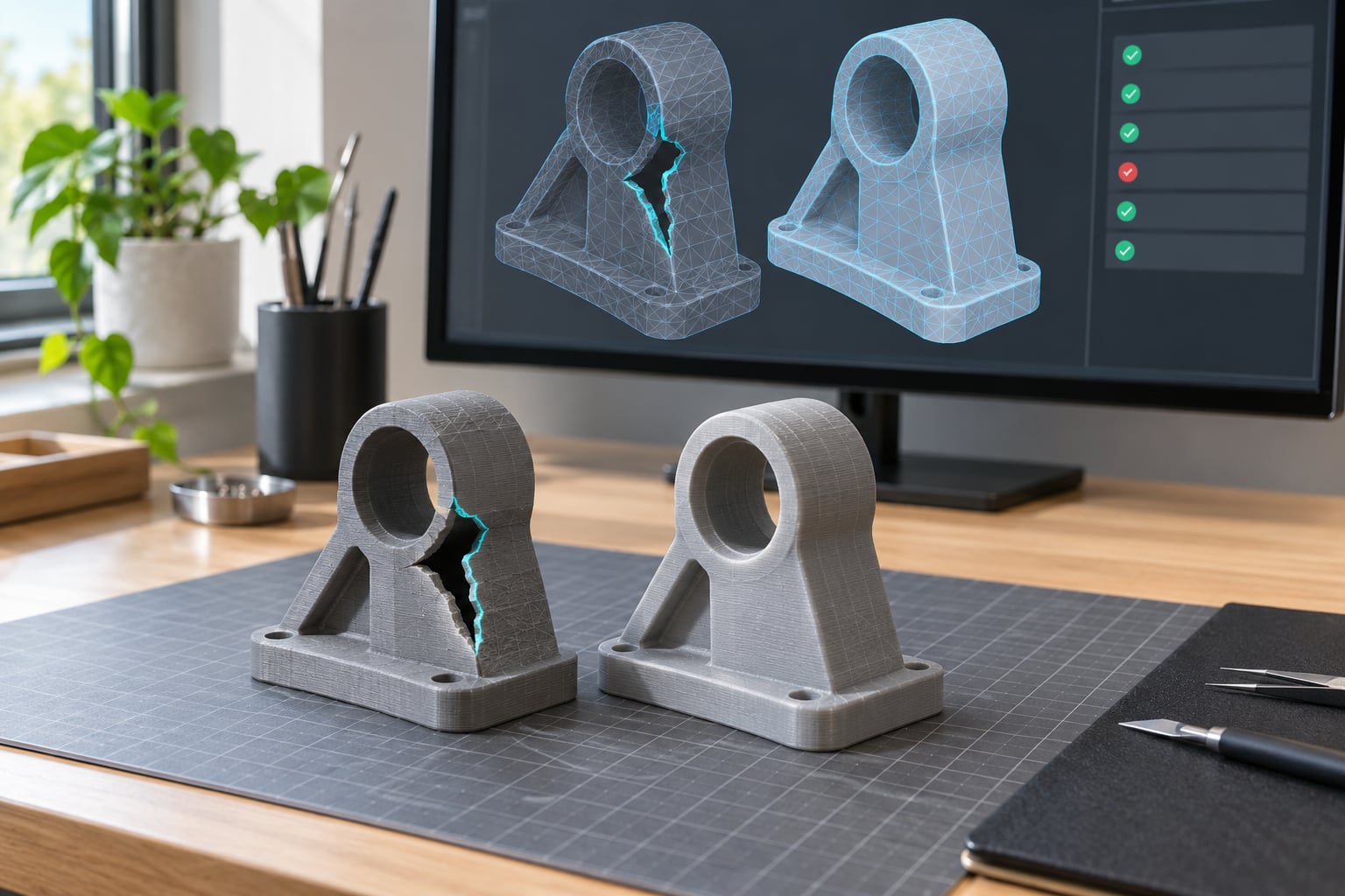
A broken STL mesh is a model whose triangles do not form one closed, watertight solid, and the slicer either refuses it outright or prints it as a solid block. Learning how to repair a broken STL mesh takes about 20 minutes on a small file with Meshmixer or your slicer’s built-in fix, and the tooling is free.
Most breakage comes from somewhere boring: a CAD export, a 3D scan, an AI-generated model, or a marketplace download. The fix is usually a diagnosis pass followed by closing holes, welding duplicate vertices, and recalculating normals.
Table of Contents
- What You Need
- Step-by-Step: Diagnose and Repair the STL
- Step 1: Make a Backup and Inspect the Mesh
- Step 2: Run a Mesh Error Check
- Step 3: Select and Remove Faulty Geometry
- Step 4: Close Small Holes and Boundary Gaps
- Step 5: Repair a Broken STL Mesh with Surface Reconstruction
- Step 6: Fix Non-Manifold Edges and Overlapping Faces
- Step 7: Recalculate Normals and Check Orientation
- Step 8: Export, Recheck, and Test-Slice the STL
- Common Mistakes
- Frequently Asked Questions
- Can a broken STL mesh always be repaired?
- What is the easiest software to repair an STL file?
- Why does my repaired STL look different from the original?
- Does STL repair recover missing 3D model details?
- How do I know if an STL is watertight?
- Should I use binary STL or ASCII STL after repairing a mesh?
- Conclusion
What You Need
Start by duplicating the original file. Repair tools make irreversible edits, and you want the untouched version available if a step goes wrong.
Then you need a mesh editor and a slicer. Both are free. Windows 3D Builder comes with Windows 10 and 11 and is the shortest path for beginners: right-click the STL in File Explorer, open it, and let the built-in repair highlight the bad region. Blender’s 3D Print add-on covers manual work, and Meshmixer’s Inspector is still the most-referenced way to actually see where the open edges are.
If you still have the original CAD file, exporting again from the source beats repairing by a wide margin. A broken mesh is a symptom of a closed-surface problem in the CAD model, and re-exporting after a fillet or a solid operation usually fixes it for good.
One thing to expect: menu labels drift between versions. Analysis in Meshmixer, Mesh Check in Blender, Repair in PrusaSlicer. The names change more often than the operations do.
Step-by-Step: Diagnose and Repair the STL
Step 1: Make a Backup and Inspect the Mesh
Load the copy into your editor and frame the whole model first. You are looking for four things: visible holes, stray floating triangles, surfaces that appear twice, and shells hanging off in space.
Switch to wireframe or face mode. Solid shaded view hides a surprising amount of damage. Then open the statistics panel and note the vertex, edge and face counts, because those numbers are your baseline for checking whether a repair did something sensible or quietly shredded the model.
Verify: you can see the whole model without anything clipped, and you know roughly where the trouble is.
Step 2: Run a Mesh Error Check
Every serious editor has a validator. In Blender, the 3D Print add-on runs a Mesh Check from the sidebar. In Meshmixer, Analysis > Inspector draws the problems straight on the model. MeshLab reports similar figures under its quality filters.
The findings you will actually hit:
- Non-manifold edges – an edge shared by three or more faces instead of exactly two.
- Open boundaries – edges belonging to a single face. These are holes.
- Overlapping or duplicate faces – two triangles sitting in the same place.
- Inverted normals – faces wound the wrong way, so they point inward.
- Self-intersections – a face passing through another face.
The reports are not identical between applications or versions, so treat the list as a set of leads rather than a score. Verify: you have a named defect and a location for each one.
Step 3: Select and Remove Faulty Geometry
Not every flagged item should be deleted. Loose faces floating inside a cavity, zero-area triangles and leftover vertex points are safe to remove, because they contribute nothing to the surface.
Isolate the selection first, look at it from two angles, and only then delete. Blender users do this with Separate by loose parts, then Select All by Trait. Meshmixer has a similar isolate workflow under its component selections.
Small disconnected shells are the judgement call. A speck the size of a pixel is debris. A shell the size of your thumb might be a real feature that came loose during export.
Verify: re-run the error check. The count of loose geometry should have dropped and nothing visible should have disappeared.
Step 4: Close Small Holes and Boundary Gaps
Small holes are the friendliest defect to fix. In Blender, select the boundary loop, hover over an edge and press F to fill, or use Bridge Edge Loops where the gap needs an actual face rather than an n-gon. In Meshmixer, the fill-hole operation takes a boundary loop and patches it directly.
Patching is safe when the hole is a few triangles across and sits on a flat or gently curved area. It stops being safe on a curved surface, where a flat patch shows as a dent under a matte finish.
If a missing region is large, or sits across a curve, rebuild it from a cross-section or go back to the CAD source. A patch that looks acceptable in a shaded view often looks wrong in a slice preview, because the slicer sees the whole outline at once.
Verify: the open-boundary count in the error check drops to zero, or to only the boundaries you deliberately kept.
Step 5: Repair a Broken STL Mesh with Surface Reconstruction
Surface reconstruction is the right answer when the geometry is noisy rather than broken: dense scanner data, photogrammetry shells, or an AI-generated mesh with skin rather than structure underneath.
The workflow is straightforward. Select the damaged region, run a voxel remesh or Meshmixer’s surface reconstruction, adjust the resolution, and compare the result against the original. Higher voxel resolution preserves more detail and produces a far heavier file, so it is a balance rather than a maximum.
Here is the warning worth reading twice. Reconstruction rounds sharp edges, softens embossed text, and fills hollow cavities and internal lattices. People print resin models with an internal hollow to save material and cure time, and an automatic fix will happily turn that into a solid brick.
Verify: compare the reconstructed model against the untouched copy side by side and confirm no detail you needed has flattened out.
Step 6: Fix Non-Manifold Edges and Overlapping Faces
Non-manifold geometry is where three or more faces meet on the same edge. It usually arrives from a CAD export after a Boolean operation, where the tool left a sliver of coincident geometry behind.
Work in this order. Separate by loose parts to see the real number of shells. Merge by distance at a small threshold to weld coincident vertices without moving anything. If two shells simply touch, union them rather than trying to patch the contact line. For stubborn spots, select just that area and reconstruct only that area.
Inspect every repair from several angles. Non-manifold errors hide best at grazing viewpoints.
Verify: the non-manifold count reaches zero and the model still measures the same in millimetres as it did before.
Step 7: Recalculate Normals and Check Orientation
Winding order decides which way each face points. Get it wrong and some slicers treat the surface as inside-out, which produces missing top layers or a part that renders as a shadow.
Blender recalculates outside normals from the inside of the object with Shift+N, then N sets every face to point outward. Meshmixer has a recalculate normals operation in the same analysis area as the Inspector.
Confirm it visually. Use a lit solid view or a backface visualisation option, and the wrongly facing triangles light up as a patch of dark or contrasting colour. An evenly shaded surface means the normals are consistent.
Verify: no dark patches remain in the backface view.
Step 8: Export, Recheck, and Test-Slice the STL
Export as STL and keep the scale units straight. Blender’s export panel asks about scale and applies modifiers; leaving those alone is usually right. Binary STL is the smaller, faster default, and ASCII is easier to read when you need to inspect a file by eye or repair it with a text editor.
Reload the exported file into your slicer rather than trusting the editor’s preview. Slicers read the file exactly as a printer would, so any error that survived the export shows up here.
Check the error report, look at the slice preview for stray islands, and print a small section when the geometry is mission-critical. That last step saves a lot of material, because a mesh can pass every automated check and still surprise you on the bed.
Verify: no error messages, and the preview shows the shape you expected.
Common Mistakes
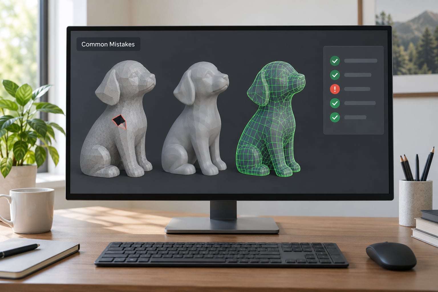
Running automatic repair on the whole model with default settings is the most common way people make a bad file worse. It happily fills cavities, rounds corners and deletes small features it considers noise.
Merging by distance with too large a threshold collapses nearby separate parts into one lump, which is why the threshold should stay small and you should check the model’s dimensions afterwards.
Assuming a clean error report means printability is the other big one. Repair fixes the mesh, not the design. Thin walls below your nozzle width, wrong scale, and impossible overhangs all survive a perfectly watertight repair untouched.
A few habits that pay off: keep the untouched backup, prefer binary STL for anything going to a slicer, and save the repaired copy under a new name so you can compare the two files in the same slicer session.
Frequently Asked Questions
Can a broken STL mesh always be repaired?
Usually, yes. Most breakage is holes, duplicate vertices, stray shells or flipped normals, and all of those are recoverable. What cannot be recovered is geometry that was never in the file. A scan with missing detail and an AI-generated model with skin instead of structure can be made watertight, but the result will not be the object you thought you had. When large regions are gone, re-scanning or remodelling beats patching.
What is the easiest software to repair an STL file?
For most people, Windows 3D Builder. It ships with Windows, opens from a right-click on the file, marks the damaged region and repairs it in a few clicks. Free PrusaSlicer and Bambu Studio have a similar repair option. Move to Meshmixer or Blender when you need to see the error and control exactly what changes, which is the proper way to learn how to repair a broken STL mesh.
Why does my repaired STL look different from the original?
Automatic repair treats anything it cannot interpret as noise. Hollow cavities get filled, thin ribs disappear, and sharp edges get rounded. Voxel remeshing adds more of the same, because it rebuilds the surface from a volume grid at a chosen resolution. If the difference is unacceptable, repair only the broken regions by hand instead of running a whole-model fix, and export from the original CAD file if you still have it.
Does STL repair recover missing 3D model details?
No. Repair works on geometry that exists. It can close a hole so the model becomes watertight, but it cannot know what was supposed to be inside that hole. Tools such as Meshmixer and Netfabb will fill the gap with a plausible surface, which is fine for a figurine and wrong for a mechanical part that needs a specific wall thickness. Missing detail means remodelling or re-scanning.
How do I know if an STL is watertight?
Run a mesh error check and read the open boundary count. Watertight means zero open edges, every edge shared by exactly two faces, and one connected shell with normals pointing outward. The practical confirmation is your slicer: load the repaired file and check whether it still reports an error. Slice the preview too, since stray islands and floating shells show up there even when the mesh passes a check.
Should I use binary STL or ASCII STL after repairing a mesh?
Binary, for almost every case. It is a fraction of the file size and loads faster in slicers, which matters once you are handling scanned models with millions of triangles. ASCII is a plain text format you can open in a text editor, which makes it useful when a file is corrupted at the byte level or when you want to inspect geometry manually. Both hold identical mesh data, so the choice is file handling, not quality.
Conclusion
Start by duplicating the file and running a mesh error check before you change anything. The whole workflow of how to repair a broken STL mesh comes down to four moves: delete loose geometry, close open boundaries, weld duplicate vertices, and recalculate normals. Then export, reload in your slicer, and look at the slice preview.
A watertight mesh slices cleanly, but watertight is not the same as printable. Scale, wall thickness, overhangs and supports are still design decisions, and no repair tool will make those for you.