Blender is genuinely good enough to take a beginner from a blank scene to a finished plastic part, as long as you treat it as a mesh modeler rather than a CAD tool. The blender for 3d printing workflow for beginners is really six stages: set the scale, model the part, clean the mesh, export it, load it into a slicer, and only then hit print. Most first-print failures come from skipping stage three, not from bad modeling.
The catch is that Blender does not know your nozzle is 0.4mm wide. It will happily let you model a 0.1mm wall that your printer cannot produce, and it will export a broken shell without warning you. That gap between what Blender draws and what a printer can physically make is the whole reason this workflow exists.
The rest of this guide walks through that workflow stage by stage, with the exact menu paths for Blender 4.x, the numbers that matter for wall thickness and layer height, and a symptom-by-symptom list of common mistakes with the fix for each. I have kept it neutral on purpose: no add-on is required, no paid tool is pushed, and nothing is interpolated from a vendor’s marketing page.
Table of Contents
- What You Need
- Blender for 3D Printing Workflow for Beginners: Step by Step
- 1. Set Up Blender for 3D Printing
- 2. Model Dimensions and Geometry
- 3. Check and Repair the Mesh
- 4. Export a Watertight STL or 3MF
- 5. Import the Model Into a Slicer
- 6. Orient, Support, and Slice the Model
- Common Mistakes
- Frequently Asked Questions
- Should I use STL or 3MF when exporting a 3D model from Blender?
- What file format should I use in Blender for resin printing?
- How do I know whether a Blender model is watertight?
- What wall thickness should a beginner use for FDM printing?
- Can beginners use Blender for functional parts instead of CAD software?
- Why does my model look correct in Blender but fail in the slicer?
- Conclusion
What You Need
Four things, and only one of them is complicated. If you have items one and two, you can model, export and slice today without buying anything.
- Blender 4.x or newer. Free, runs on Windows, macOS and Linux, and handles parts far larger than a printer’s build volume. Blender 3.x works for this workflow too, but a few menu names differ.
- A slicer. PrusaSlicer, OrcaSlicer or Cura all import STL and 3MF files and turn them into G-code. OrcaSlicer and PrusaSlicer are the smoother options if you have never used one; Cura is still perfectly capable, its interface just hides more behind a plain-text settings box.
- A printer, or at least a preview. You can run the entire workflow without hardware and simply watch the sliced preview layer by layer. That preview is more diagnostic than most beginners expect.
- Optional repair helpers. Blender’s built-in 3D Print Toolbox add-on is the main one. MeshLab or Meshmixer are useful if you regularly import geometry from other tools, and a digital caliper matters only once you start checking real-world dimensions against your prints.
Computer power is not the constraint beginners expect it to be. A phone stand or a name plate is a few thousand polygons and any laptop from the last decade handles that in seconds. Heavy subdivision sculpts and Boolean chains on imported CAD files are what actually tax a machine.
Blender for 3D Printing Workflow for Beginners: Step by Step
One honest note before the steps: the menu paths below follow Blender 4.x. Older releases moved a few of these options, and Blender 2.8-era tutorials online will send you looking for panels that no longer exist. The concepts have not changed, only the addresses of the buttons.
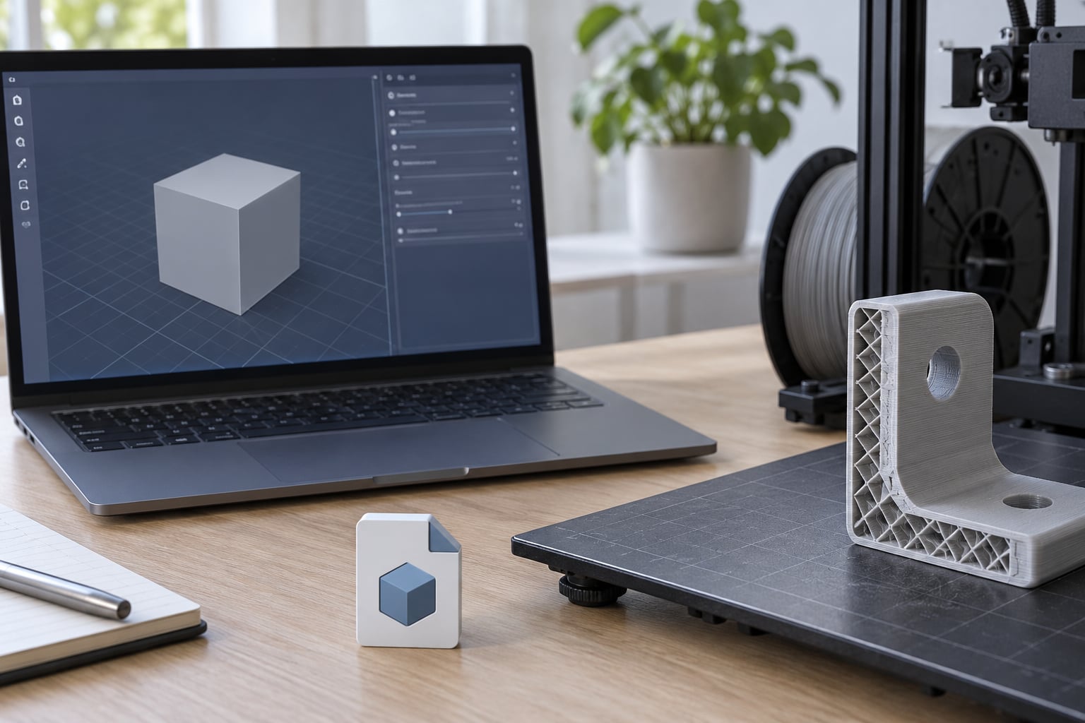
Use a small test model for your first run through this workflow. A cube scaled to 20mm on a side prints in a few minutes, teaches you every stage, and costs almost nothing if something goes wrong. Print it before you try anything you care about.
1. Set Up Blender for 3D Printing
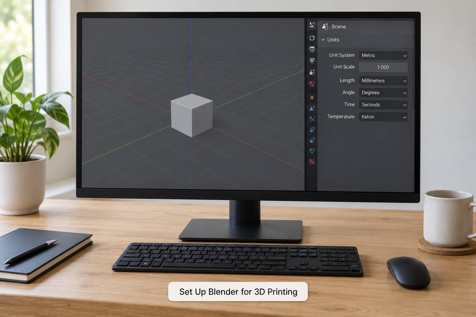
Blender’s default scale is one unit equals one meter, and that single fact causes most of the wrong-size imports beginners complain about. Open the Properties editor and go to the Scene tab, then set the unit system to Metric and the length unit to Millimeters. Now a value of 20 in Blender means 20mm, which is the number your slicer expects.
Leave the scene scale factor at 1.0 while you work. A non-1.0 factor introduces a conversion that most people forget about, and the result is a part that arrives at the slicer hundreds of times too large or too small.
Next, set the workspace. The Layout workspace is fine for modeling, but the 3D Print Toolbox panel lives in the sidebar, so make the sidebar visible with the N key and hover over the workspace tab with two overlapping squares to see the available panels. The scale tool in the toolbar measures directly on the model and is faster than reading coordinates.
Two more habits worth setting now. Turn on snapping with the magnet icon and Tab, so vertices land on a regular grid instead of at arbitrary coordinates. And work in Object Mode unless you are deliberately editing vertices, because object mode keeps the modifier stack and transform data intact.
2. Model Dimensions and Geometry
Model the part at its real size from the start. If you want a 90mm phone stand, type 90 into the fields rather than scaling a unit cube by eye, and then apply the scale with Ctrl+A followed by S in Object Mode. Unapplied scale is one of the most common causes of a distorted export.
Start from clean primitives. A cube, a cylinder or a plane gives you predictable topology that repairs easily, and most functional parts are combinations of those. Add a cube with Shift+A, scale it, and subdivide with a Bevel modifier to round the edges rather than hand-building rounded geometry.
Keep the mesh simple. Unapplied subdivision, transparency, thin single-sided planes and duplicate internal surfaces all behave differently once they reach a printer. A plane has no thickness, so it exports as a zero-volume shell; give it real depth with a Solidify modifier instead.
Watch for floating geometry. A small detail sitting 2mm away from the main body looks fine in the viewport and prints as a loose flake that knocks around the bed. If a piece does not touch the body, connect it or merge it.
3. Check and Repair the Mesh
A watertight (manifold) mesh is one with no holes, no loose edges and no internal walls, so the slicer can compute a solid volume without guessing. Non-manifold geometry is anything that breaks that: an edge with only one face attached, an edge with more than two, or a face floating inside another shell. The slicer has no reliable way to fill those, so it either warns, patches them badly, or prints the wrong shape silently.
Run the checks in this order. It matters, because repairing out of order tends to spread the problem to nearby vertices instead of fixing it.
- Enable the add-on: Edit, Preferences, Add-ons, search for 3D Print Toolbox, tick the box.
- Open the sidebar in Object Mode and select your model, then run Check All in the 3D Print panel.
- Select the offending geometry with Select All by Trait, which highlights non-manifold edges, loose verts and faces.
- Enter Edit Mode, select all, then Mesh, Clean Up, Merge by Distance to weld duplicate vertices.
- Mesh, Normals, Recalculate Outside to fix any flipped normals, which is Shift+N in the default keymap.
- Exit to Object Mode and run Check All again. Repeat until it is clean.
For a stubborn mesh, a voxel Remesh modifier at 0.5 to 1mm followed by Smooth will often produce a clean manifold surface, at the cost of sharp detail. Use it on organic shapes, not on anything with tight tolerances. Automatic repair is a fallback, not a substitute for looking at your model: an automated pass can close a hole you wanted to keep and leave open one you wanted sealed.
If the model came from another CAD program, problems you never created often arrive with it. One recurring pattern is STEP files that import with widespread non-manifold edges because of how the source tool converted the surfaces. Repair in Blender, not in the slicer, since a slicer fix that works on the outside can break a cutout elsewhere on the part.
4. Export a Watertight STL or 3MF
Yes, Blender exports STL files directly, and the export takes about ten seconds once your model is clean. The path is File, Export, then Stl (.stl), and the options you touch matter more than most beginners expect.
- Select the object you want in Object Mode so you control exactly what leaves the scene.
- Go to File, Export and choose Stl (.stl).
- Set Scale to 1.0. Anything else rescales the mesh during export.
- Tick Apply Modifiers so Solidify, Bevel and Remesh results are baked in rather than silently ignored.
- Tick Use Selection Only if you exported with an active selection, otherwise your whole scene goes into one file.
- Choose Binary for the file format. Binary is far smaller and slicers read it faster; ASCII is larger and only useful when you need to read the coordinates by hand.
Export to a dedicated folder and give files meaningful names. When you are on your fourth iteration of the same bracket, part-name-v3.stl beats part-name-final-final-2.stl.
Then reopen the exported file before moving on: File, Import, Stl (.stl). Check that the size matches what you modeled and that the shape has not shifted. An export that silently changed scale is far cheaper to catch now than after an eight-hour print.
3MF is the format worth learning next. It stores units, colour and material information, and Blender exports it from the same menu. For a beginner printing plain single-material parts, STL is enough, but 3MF avoids a whole class of unit problems.
5. Import the Model Into a Slicer
Open your slicer, drag the STL or 3MF in, and then confirm three things before slicing anything. First, the measured size on the model matches your intent, checked with the slicer’s own scale readout rather than by eye against the build plate grid. Second, the correct printer profile is selected, since profiles carry the build volume, nozzle size and retraction settings. Third, the material profile matches the filament or resin you will actually use.
Read the warning messages. A non-manifold warning, an unsupported shell count or an empty model after import all point back to stage three. The most misleading slicer behaviour is silent repair: it fixes a hole you did not know about, the print runs to completion, and the part comes out subtly wrong.
If the model imports at an absurd size, the usual cause is a unit mismatch rather than broken geometry. A part that should be 40mm arriving as a five-metre object almost always traces back to the scene scale or an unapplied object scale, not to the slicer.
6. Orient, Support, and Slice the Model
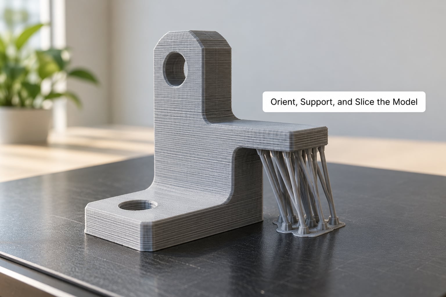
Orientation changes print time, layer count and strength more than any other decision you make. Put the largest flat face on the bed, because layers applied across a wide base are stronger and quicker than layers stacked along a tall axis. A 20mm cube printed upright and the same cube on its side take wildly different amounts of time for identical geometry.
Add supports only where the geometry actually overhangs. A surface angling down at 45 degrees or steeper is usually fine unsupported; anything past roughly 60 degrees will droop into a mess on FDM. Resin printers need far less support because the liquid resin supports the print, and supported resin prints are harder to clean.
For a beginner FDM print, 0.2mm layer height and around 10 to 20 percent infill are sensible starting values. Infill above about 30 percent rarely adds strength that a higher perimeter count does not give you more cheaply. The perimeter count and wall thickness do most of the real work.
Then slice and watch the preview. Check the first layer for bed contact and the top of the model for gaps, stringing paths or a section the toolpath is skipping. The preview is a free diagnostic pass, and it catches more mistakes than the print itself will.
Common Mistakes
Most of what goes wrong falls into a handful of patterns, and each one has a direct fix. Each entry below names the symptom you would see in Blender or the slicer, the stage that caused it, and what to change.
- Model imports at the wrong size. Usually the scene scale is not set to millimeters, or the object scale was never applied. Set the length unit to millimeters with a scene scale of 1.0, then select the object and use Ctrl+A, S in Object Mode.
- Slicer warns about non-manifold geometry. A hole, loose edge or internal face in the mesh. Run the 3D Print Toolbox checks, merge by distance, recalculate normals, then re-check.
- Exported shape differs from the viewport. Modifiers were left unapplied, or Use Selection Only was off so other objects came along. Tick Apply Modifiers and Use Selection Only in the export dialog.
- Print has holes or missing sections. Zero-area faces, T-junctions, or a plane exported with no thickness. Add a Solidify modifier for real wall depth and re-check the mesh.
- Surface is dimpled or wrongly shaded. Flipped normals on part of the mesh. Run Mesh, Normals, Recalculate Outside, then check the shading in Material Preview.
- Loose fragments on the bed. Floating geometry, or a second shell that never merged with the body. Use Select All by Trait to find the loose geometry, then delete it or connect it to the body.
- Bottom layers look rough or droop. The orientation was chosen for looks rather than for the build plate. Reorient the part so its largest flat face sits on the plate.
- Stringy, cluttered underside. Supports were placed over the whole model. Delete them and keep only supports under true overhangs past roughly 60 degrees.
- Thin walls vanish mid-print. The walls are thinner than the nozzle can produce. Raise wall thickness to at least three nozzle widths, or switch to a smaller nozzle.
One habit covers more failures than any other: run Check All again after every significant edit. Geometry that was clean ten minutes ago is not necessarily clean now, and a Boolean operation or an extrude is exactly where that changes.
Frequently Asked Questions
Should I use STL or 3MF when exporting a 3D model from Blender?
Use STL for a first project and for single-material parts. It is the format every slicer reads without complaint, and its one real weakness is that it stores no units or colour data. Move to 3MF once you print in multiple colours or keep hitting unit mismatches, because 3MF carries scale and material information inside the file instead of leaving your slicer to assume.
What file format should I use in Blender for resin printing?
STL works for resin printing exactly as it does for FDM, and resin has no special format requirement. What does change is your modeling approach. Resin printers handle fine detail and near-vertical surfaces far better than FDM, so you can model thinner walls and steeper overhangs. Leave at least a small base contact area, because a part that touches the build plate at a single point is hard to remove.
How do I know whether a Blender model is watertight?
Open the sidebar, select the object, and run Check All in the 3D Print Toolbox panel. A manifold result means every edge is shared by exactly two faces. You can confirm visually by entering Edit Mode, selecting all, and enabling Face Select in the header: a fully enclosed surface selects every face at once, and any unselected face is a hole.
What wall thickness should a beginner use for FDM printing?
Use a minimum of three times your nozzle diameter, so three perimeters on a 0.4mm nozzle means a 1.2mm wall. Going thinner produces walls the extrusion cannot reliably fill, and they often look fine in the viewport but fail halfway up the print. For a load-bearing bracket, four to five perimeters usually does more good than raising the infill percentage.
Can beginners use Blender for functional parts instead of CAD software?
Blender works well for brackets, stands, enclosures and adapters, because those are mostly shapes and cuts. It is a poor fit for parts that must snap together, slide in a slot or hold a tight bolt hole, since Blender has no parametric constraints and no tolerance control. For that kind of part, CAD tools such as Fusion 360, Onshape or FreeCAD model more predictably.
Why does my model look correct in Blender but fail in the slicer?
Because a mesh can look right on screen and still be mathematically broken. The usual culprits are holes smaller than a pixel, flipped normals, duplicate vertices, or an unapplied Solidify modifier that exports as an open shell. Run the 3D Print Toolbox checks, recalculate normals, apply every modifier, and then reopen the exported file in Blender to confirm it arrived intact.
Conclusion
The blender for 3d printing workflow for beginners is a repeatable loop: set millimeters, model at real size, clean the mesh, export with modifiers applied, then verify in the slicer before printing. Each stage takes minutes, and the checking stage is the one that decides whether the print succeeds.
Start with a cube scaled to 20mm. Export it, import it, read the slice preview, and print it. Once that small loop feels automatic, move to something with a cutout and a wall thickness decision, because that is where the real judgment starts.