For most desktop 3D printers, the minimum printable wall thickness is two full extrusion lines wide, which means roughly 0.8 to 0.9 mm on a standard 0.4 mm nozzle, and 1.2 mm for a typical functional part. Load-bearing geometry wants 2.0 mm or more, and resin printers can go thinner.
The rule I fall back on: if a wall is thinner than two full extrusion lines, the slicer is improvising, and improvised walls are where the gaps start.
Those are starting points, not laws. Wall thickness guidelines for 3D printing shift with your nozzle, your material, the load the part carries, and how the part sits on the build plate. I have wasted more filament on a part that needed a 0.4 mm gusset than I care to admit. This guide gives you the numbers, the math behind them, and a way to test what your own machine actually holds.
Table of Contents
- Wall Thickness Guidelines for 3D Printing at a Glance
- What Is the Best Wall Thickness for 3D Printing?
- How thick should a wall be for 3D printing?
- The strongest wall is not always the right wall
- How Does Wall Thickness Affect Strength and Printability?
- Wall Thickness Guidelines by 3D Printing Process
- FDM
- SLA and MSLA resin printing
- SLS and MJF laser sintering
- PolyJet and metal powder processes
- Wall Thickness Guidelines by Material
- How to Choose a Wall Thickness for Your Part
- What Is a Good Wall Thickness for Different 3D Printed Parts?
- Wall Thickness vs. Perimeters, Shells, and Infill
- How to Test Wall Thickness Before Printing a Final Part
- Frequently Asked Questions
- What is the minimum recommended wall thickness for 3D printing?
- What is a good wall thickness for 3D printing PLA?
- How many wall loops are recommended for 3D printing?
- What can I do if my 3D printing walls are too thin?
- How thin is too thin to 3D print?
- Should I increase wall thickness or infill for strength?
- Conclusion
Wall Thickness Guidelines for 3D Printing at a Glance
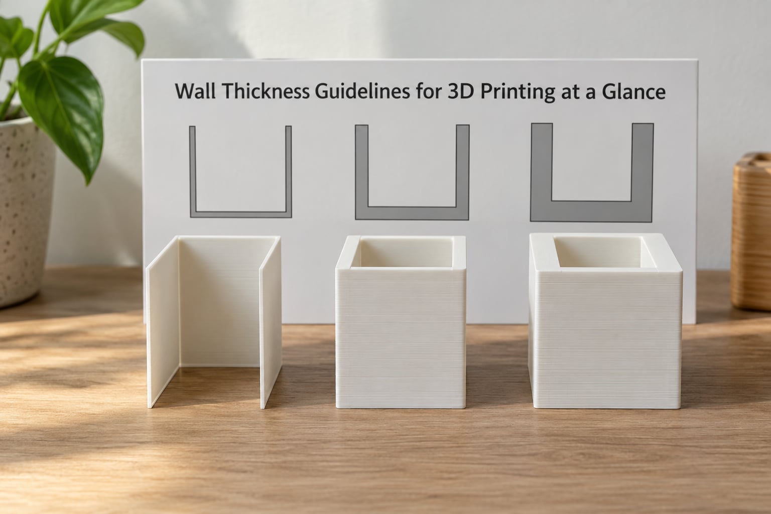
Here is the short version. Every number below assumes a well-calibrated machine printing a solid, well-extruded part.
| Process or material | Minimum | Recommended | Load-bearing |
|---|---|---|---|
| FDM, 0.4 mm nozzle | 0.8 mm | 1.2 mm | 2.0 mm |
| FDM, 0.2 mm nozzle | 0.4 mm | 0.6 mm | 1.2 mm |
| FDM, 0.6 mm nozzle | 1.2 mm | 1.8 mm | 3.0 mm |
| SLA / MSLA resin | 0.6 mm | 0.8 mm | 1.5 mm |
| SLS nylon | 0.6 mm | 1.0 mm | 2.0 mm |
| MJF nylon | 0.3 mm | 0.5 mm | 1.5 mm |
| PolyJet | 0.5 mm | 1.0 mm | 2.0 mm |
| Metal SLM / DMLS | 0.5 mm | 1.0 mm | 2.0 mm |
| TPU on FDM | 1.2 mm | 2.0 mm | 3.0 mm |
You will notice service guides quote different FDM minimums. Some say 0.8 mm, some insist on 1.2 mm. Neither is wrong: 0.8 mm is the reliable print floor for a non-critical part, while 1.2 mm is where a functional part stops worrying you. Treat the minimum as the point where the slicer can lay a complete wall, and the recommended column as where you actually want to live.
What Is the Best Wall Thickness for 3D Printing?
There is no single best number, and the reason is worth understanding. Wall thickness does two jobs at once: it gives the part stiffness and strength, and it tells the slicer how many perimeter loops to draw so the wall comes out solid.
Nominal thickness is the wall you modeled in CAD. Effective thickness is what the slicer actually builds, and it depends on extrusion width, wall loop count, first layer squish, and how well neighbouring lines bond. A 1.2 mm nominal wall can print as 1.3 mm if the first line bites into the second, or as a visible gap if flow is too low.
How thick should a wall be for 3D printing?
Start at 1.2 mm for a general functional part, add a second perimeter loop or a rib before you add thickness, and go to 2.0 mm only when the part genuinely carries load or sees impact.
The strongest wall is not always the right wall
Thickness buys stiffness, not toughness. A wall that fails because layers separated is a layer-bonding problem, and piling on more layers will not fix it. Very thick walls also cool unevenly, so on larger parts they can split along layer lines while a thinner ribbed design holds together better.
How Does Wall Thickness Affect Strength and Printability?
Stiffness scales with the square of thickness for a given material. Double the wall and it is roughly four times stiffer, which is why a thin shell with ribs beats a fat shell in most designs.
Printability moves the other way. Thick walls mean longer time per layer, more heat trapped in the part, and a bigger thermal gradient between the outside and the core, which is where warping and layer splitting come from. Print time and filament use rise close to linearly with wall area, so a 2 mm wall on a 100 mm cube takes meaningfully longer than a 1.2 mm wall with internal ribs.
Layer adhesion is the other factor. Layer bonding depends on extrusion temperature, speed, and how much the previous layer is disturbed before the next one lands. Walls do not change that relationship, but thin vertical features near the bed fail first because they get no second chance, and they snap off during support removal.
Surface quality tracks thickness closely too. More perimeter lines mean fewer visible layer lines, so a thicker wall hides slicer artefacts and prints smoother. Cosmetic parts benefit from that even when they carry no load at all.
Wall Thickness Guidelines by 3D Printing Process
FDM
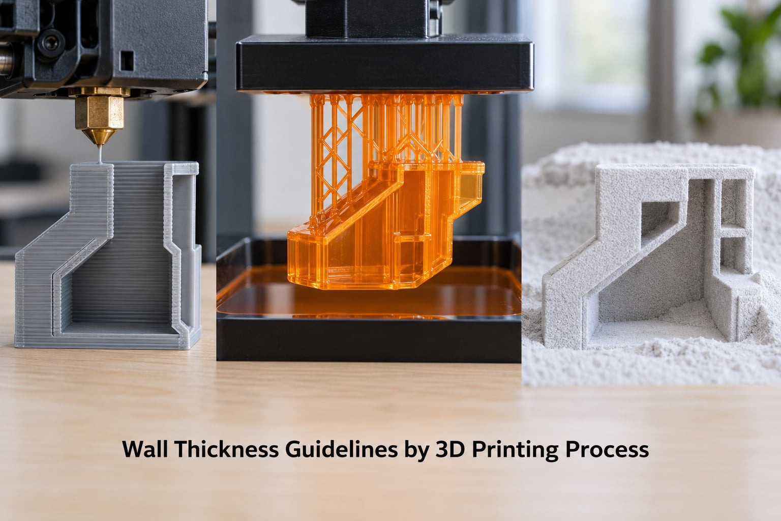
FDM wall thickness is locked to extrusion width. A wall must be at least two line widths wide so both perimeters print as complete loops, and the practical rule is minimum equals two times your extrusion width.
| Nozzle diameter | Typical extrusion width | Minimum wall | Recommended wall |
|---|---|---|---|
| 0.2 mm | 0.25 mm | 0.4 mm | 0.6 mm |
| 0.4 mm | 0.45 mm | 0.8 mm | 1.2 mm |
| 0.6 mm | 0.65 mm | 1.2 mm | 1.8 mm |
| 0.8 mm | 0.85 mm | 1.6 mm | 2.4 mm |
Going below two line widths means the slicer has to split a bead or fake a thin wall with variable line width, which is where visible gaps between lines show up. Large extrusion widths of 0.5 mm and up can also fail to merge cleanly with their neighbours on some machines, so if your walls look striped, check flow and retraction before blaming your design.
SLA and MSLA resin printing
Resin has no extrusion width to satisfy, so its floor is set by peel forces and light penetration rather than by nozzle geometry. Walls of 0.6 mm print reliably and 0.8 mm is the comfortable default. Thin vertical walls on a resin part are more fragile than the same wall on FDM, because there is no infill and no perimeter to fall back on.
SLS and MJF laser sintering
Powder-bed processes need no support and need almost no minimum at all, because the surrounding powder supports the part. Laser sintering guidance asks you to keep walls above 0.6 mm for reliability and to orient thinner walls horizontally in the build rather than vertically. MJF can go thinner still: about 0.3 mm for short walls facing the build plane, and 0.5 mm for walls that face up.
PolyJet and metal powder processes
PolyJet prints at a very high resolution and tolerates roughly 0.5 mm walls, but its materials are brittle, so go thicker for anything that will be handled. Metal SLM and DMLS parts behave like the casting or forging they replace, so 0.5 mm is the manufacturing floor and thin features usually need a redesign rather than a printer change.
Wall Thickness Guidelines by Material
Material changes how you interpret the same number. Some of the guidance below is expressed as an adjustment to a baseline wall rather than an absolute value, because the failure mode differs so much between a rigid filament and a soft one.
| Material | Minimum wall | Recommended | What to watch |
|---|---|---|---|
| PLA | 0.8 mm | 1.2 mm | Brittle in snaps; prints sharpest and most accurately |
| PETG | 0.8 mm | 1.2 mm | Stringy and flexible at thin walls; slightly softer to machine |
| ABS | 1.0 mm | 1.6 mm | Add roughly 0.2 mm over PLA; warps without an enclosure |
| ASA | 1.0 mm | 1.6 mm | Same handling as ABS, better UV and heat resistance |
| TPU | 1.2 mm | 2.0 mm | Thin walls bend and collapse; flexible resin behaves similarly |
| Nylon | 1.0 mm | 1.6 mm | Hygroscopic, so dry filament and add clearance for swelling |
| Carbon fibre composite | 1.0 mm | 1.6 mm | Abrasive; hardened nozzle and stiffer layers, brittle in thin sections |
| Standard photopolymer resin | 0.6 mm | 0.8 mm | Brittle at thin walls; toughened resin widens that margin |
| Engineering resin (PA, toughened) | 0.8 mm | 1.2 mm | Behaves far closer to a machined part than to a toy filament |
TPU deserves its own note. Most generic thickness advice fails on flexible material, because a 1.2 mm TPU wall that is fine under compression folds over under load. Two millimetres is a better floor, and slow print speeds with generous flow help the wall hold its shape instead of sagging between layers.
If your material is not on this list, the pattern still holds. Add about 0.2 mm to the baseline for anything that warps or flows, and stay at the baseline or below for anything rigid and stable.
How to Choose a Wall Thickness for Your Part
Run through these questions in order and the number falls out of them.
- How big is the part? Larger parts need thicker walls for the same stiffness, but they also warp more. A large flat panel at 1.2 mm with a few ribs usually beats the same panel at 3 mm.
- Which direction does the load run? Put the main force in the X-Y plane. FDM parts are far weaker between layers, so a wall that carries load along its face is much stronger than one loaded across its height.
- Is it impact or static load? Static loads respond to stiffness and thickness. Impacts and snaps respond to layer bonding and notch shape, so round the root of a clip rather than thickening it.
- Does it see heat or chemicals? ABS and ASA tolerate heat better than PLA; PETG handles oils and moisture better than either. Match the material to the environment first, then pick thickness inside that material’s range.
- How precise does it need to be? Thin walls move. A part that holds a measured tolerance needs thickness in the walls near that feature, not a global increase.
- How is it oriented? Vertical thin features print last and get no support. Anything under 1 mm standing on its own end needs a chamfer, a foot, or a slower print.
- Must the wall support itself? Self-supporting walls can lean off vertical by up to about 45 degrees. Beyond that you are into support territory and should thicken instead of angling.
What Is a Good Wall Thickness for Different 3D Printed Parts?
The same part function has a different answer depending on whether you care about looks or load, so here are concrete starting points.
| Part type | Wall thickness | Notes |
|---|---|---|
| Vase mode or decorative shell | 0.4 to 0.8 mm | One continuous loop; keep the nozzle fed and stop with the machine |
| Figurines and display models | 0.8 mm | Sub-1 mm walls are fine for miniatures; a 0.2 mm nozzle gets you there |
| Enclosures and boxes | 1.2 mm | Add screw bosses at roughly 3 mm diameter before printing |
| Brackets under moderate load | 1.6 mm | Ribs beat extra thickness; orient the load in-plane |
| Hooks and hangers | 2.0 mm | Add a 45 degree gusset where the hook meets the back plate |
| Containers and vessels | 1.2 mm | Thicken the base to three or four layers |
| Snap-fit parts | 1.6 mm | Thickness is not the fix; the stress riser at the clip root is |
| Pins, pegs and axles | 1.2 mm | These are solid features, so allow for shrinkage on FDM fit |
| Living hinges | 0.8 to 1.2 mm | Print flat, PETG over PLA, and go slow on the hinge lines |
| Threaded holes and heat-set inserts | 3.0 mm wall around the hole | The insert needs solid material in every direction, not just across the wall |
| Clear or translucent parts | 1.0 mm | Thin walls refract unevenly and show layer lines |
| Molds and forms | 2.0 mm | Thick walls resist the warping that ruins mould surfaces |
Wall Thickness vs. Perimeters, Shells, and Infill
This is the single most common confusion, so it is worth separating clearly. Wall thickness is geometry you decide in your CAD program. Wall loop count is a slicer setting that tells the printer how many times to trace that geometry.
In Cura, PrusaSlicer, OrcaSlicer and Bambu Studio the setting is called Wall Loops, Wall Line Count or Perimeters, depending on the slicer. Setting three wall loops on a 1.2 mm nominal wall does not make the wall 1.8 mm; it makes the slicer try to fit three loops inside 1.2 mm, which produces overlapping lines and a heavy, inconsistent surface.
Shells work the same way. Top and bottom shell thickness set how many layers form the ceiling and floor of the part. Keep tops at three layers and bottoms at four for a box that will be handled; increase them only if the surface will be seen edge-on or machined.
Infill sits inside the walls and does almost nothing for surface strength. When strength is the goal, adding perimeters beats raising infill percentage every time. Two or three wall loops at 20 percent infill produce a stiffer, better-finished part than one wall loop at 60 percent infill, and they print faster because the extrusion happens at high flow near the outside of the part.
Raising infill is worth it for internal cores, and only there. If you need a genuinely strong part, combine three wall loops with 40 to 60 percent infill, or skip infill altogether and use a gyroid pattern at a moderate density, which behaves better in every direction.
How to Test Wall Thickness Before Printing a Final Part
Every machine, material and nozzle combination behaves differently, so a fifteen-minute coupon beats an argument with a failed print. This is the step I skip most, and it is the step that would have told me sooner that my flow was off.
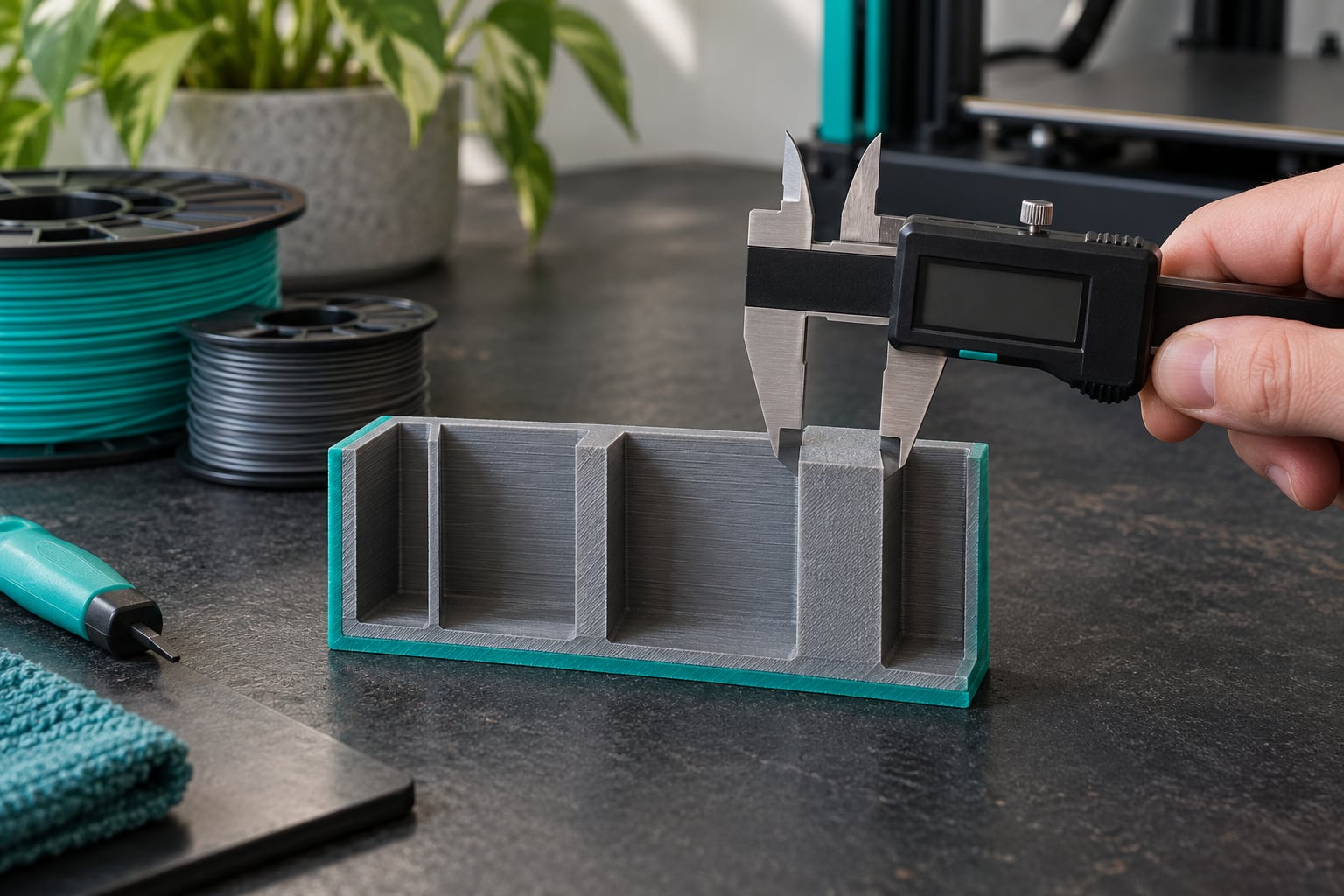
- Print a wall coupon. Model one part with walls at 0.8, 1.2, 1.6 and 2.0 mm, each as a 40 mm tall strip standing on the build plate. Strips test both layer bonding and vertical stability in one go.
- Measure with calipers. Check width at three heights including near the first layer. A consistent reading tells you your flow and extrusion width are calibrated; a tapered wall tells you it is not.
- Look for gaps between lines. Under a light, visible separation between perimeters means the wall is thinner than two full line widths. Fix the flow before you redesign anything.
- Load and flex each strip. Push sideways, then try to snap it. Record which thickness survives the force your real part will see.
- Test layer adhesion. Break one strip deliberately along its layer lines. If it separates cleanly between layers, slow the print and raise the temperature rather than adding walls.
- Write the result down. A note of material, nozzle, temperature, wall thickness and outcome makes every later print faster, and it settles arguments with other guides.
Frequently Asked Questions
What is the minimum recommended wall thickness for 3D printing?
For FDM on a 0.4 mm nozzle, 0.8 mm is the absolute minimum and 1.2 mm is the recommendation for functional parts. The minimum equals two extrusion widths, so it scales with your nozzle: 0.4 mm on a 0.2 mm nozzle, 1.2 mm on a 0.6 mm nozzle. Use 2.0 mm or more for load-bearing geometry. Resin printers can go as thin as 0.6 mm.
What is a good wall thickness for 3D printing PLA?
A 1.2 mm wall is the sweet spot for PLA parts. Anything at or above 0.8 mm prints reliably on a 0.4 mm nozzle, and 2.0 mm suits brackets and handles. PLA is stiff but brittle, so for snap fits and clips keep the wall at 1.6 mm and instead round the stress riser at the root and print the part with the load running across the layers rather than through them.
How many wall loops are recommended for 3D printing?
Two or three wall loops suits most functional prints. Two gives a clean surface and decent stiffness, three adds noticeably more strength and better layer bonding. Check the spacing before adding more: a 1.2 mm wall only fits two or three loops comfortably. Setting a high loop count on a thin model overlaps lines and gives a heavy, inconsistent surface instead of extra strength.
What can I do if my 3D printing walls are too thin?
Four fixes cover most cases. First, raise the extrusion width slightly or the flow rate so the lines merge. Second, add a wall loop or two in the slicer so the wall fills out. Third, add ribs or gussets instead of thickening, which adds stiffness without the warping of a fat wall. Fourth, reorient the part so the thin wall lies down on the plate instead of standing vertically.
How thin is too thin to 3D print?
On FDM, anything under two extrusion widths is below the limit, which means under 0.8 mm on a 0.4 mm nozzle. Below that the slicer has to split a bead, and you get gaps between lines that print as a wall in name only. A sub-millimetre wall is achievable with a 0.2 mm nozzle or variable line width, but it needs careful flow control and it is only worth it for small parts.
Should I increase wall thickness or infill for strength?
Increase the perimeters first. Walls carry surface stress, control the finish, and print at the high flow rates the extruder handles well. Infill lives inside the part and adds stiffness without improving the surface at all. A practical strong combination is three wall loops with 40 to 60 percent infill, or three wall loops with a gyroid pattern for better behaviour in every direction.
Conclusion
Start with 1.2 mm for a general functional part and 2.0 mm when it carries real load, then adjust for your nozzle before anything else. If a wall is failing, print a coupon rather than guessing, because the failure tells you whether you need more thickness, more perimeters, or better layer bonding. And when a part feels weak, reach for ribs before you reach for a thicker wall.